
BrickLink Studio Instructions Tutorial: Model to Test Build
Need instructions another person can actually follow? Start with a part-level model, organize a buildable sequence, design the pages and test the exported document. This tutorial uses a tiny downloadable exercise so you can inspect every part before applying the method to your own MOC.
Choose a parts-based workflow for physical instructions
A finished photo cannot show every hidden part, attachment or internal support. BrickLink Studio gives you a model made from individual parts, which you can organize into instruction steps. An AI steps board is a different output: it can illustrate a visual assembly story, but it does not provide the same parts-based record.
Use this workflow when someone else must recreate a physical model or when you need a part inventory. Use a presentation workflow when your objective is a short model showcase. Keeping those deliverables separate prevents a polished video from becoming accidental evidence that a design has been verified.
Download a five-part practice model
The exercise contains one 2×8 plate (3034), three 2×4 bricks (3001) and one 2×4 plate (3020). Two red bricks sit side by side on the base. One blue brick bridges their central seam, and a white plate caps it. There are four proposed steps and five parts in total.
Download the LDraw file and import it into a current version of Studio. Use this small model to inspect how imported steps appear in Instruction Maker before working on a valuable design. The file is an original coordinate-based exercise; it has not been presented as a physically tested kit. Confirm the geometry and parts in your installation, then build it if you have the pieces.
Count the parts after import. You should see five instances, including three separate 3001 bricks. If a piece is missing or has an unexpected orientation, resolve that first. Do not compensate for a wrong model by drawing a misleading instruction page.
Download the five-part practice model (LDraw) ↓
↔ Scroll sideways to read all columns
| Step | Add | Reason |
|---|---|---|
| 1 | One 2×8 base plate | Establish a stable base and camera orientation |
| 2 | Two red 2×4 bricks | Place the two supports at the same level |
| 3 | One blue 2×4 brick | Bridge the seam between the red bricks |
| 4 | One white 2×4 plate | Finish with a visible, easy-to-check cap |
Check the model before designing pages
Open the part list and confirm identifiers, quantities and colors. Then inspect the model from the sides and underside, not just the attractive front view. Look for floating pieces, overlaps, impossible insertion paths and parts that are hidden behind assemblies placed too early.
Studio’s checks can help find issues, but a clean digital appearance is not a substitute for a real build. For your own MOC, record any uncertain connection. If you are relying on a part in an unusual color, verify its availability before publishing a shopping list. Use actual part identifiers rather than guessing from a rendered shape.
Organize steps around the builder’s next action
Open Instruction Maker and review the sequence in Step Editor. For the practice file, confirm that the two red bricks appear before the blue bridge. If an import groups everything into one step, use the four-step table above as the intended sequence and assign the parts accordingly. Menu placement may vary by Studio version; the official Help Center is the reference for current controls.
For larger models, give a step one clear action. Split an assembly when several new pieces hide one another or require a confusing camera angle. Group a repeated small unit as a submodel when that makes its construction easier to understand, then show how it attaches to the larger model.
Check access as well as order. A pin inserted from the side may become unreachable after a panel is attached. A top view may hide whether a piece belongs in the front or back row. When the next action is ambiguous, change the view or split the step before adding more decorative page elements.
- Open Instruction Maker from the toolbar, or use Tool → Instruction Maker.
- Use Step Editor to inspect and organize which parts appear at each step.
- Switch to Page Design to review the printable pages.
- Use Export to produce a PDF, or PNG files with one image per page.
Review page design at the size people will use
In Page Design, inspect the added-part callout, step number, model orientation and any submodel placement. Export a draft and open that export outside Studio. A page that looks readable on a large editing canvas can become cramped on a phone or when printed.
For the practice model, a reader should be able to distinguish the two red bricks in step 2 and see that the blue brick crosses their seam in step 3. Check that no crop hides the connection. For a larger model, label orientation changes clearly and keep similar views consistent so readers do not have to mentally rotate the model without warning.
Use sufficient visual contrast, but do not make color the only clue. A grayscale printout should still communicate placement through geometry and the part callout. Inspect the first page, a typical middle page and the most crowded page before distributing the full document.
A useful Studio detail: setting a camera angle in Step View affects Page Design, but changing the view in Page Design does not set the Step View angle. If the two views disagree, check where you changed the camera; the official Step View guide explains this direction of inheritance.
Test the exported instructions with a fresh reader
Give a tester the exported instructions and loose pieces. Ask them to stop whenever they have to guess. Do not rescue the instructions by explaining every step aloud; record where a hint was necessary, then revise the document so the next reader will not need that hint.
The printable checklist below separates model errors from communication errors. A wrong quantity requires fixing the inventory. An unclear rotation may require a new view. A part that cannot be inserted requires changing the build order or the design itself. Repeat the affected section after revising it.
If you cannot physically test a connection, label that uncertainty in your release notes. Keep the editable model, exported instructions and revision notes together. A version date helps readers report a specific problem rather than referring to an unknown earlier PDF.
Create a separate showcase after checking the instructions
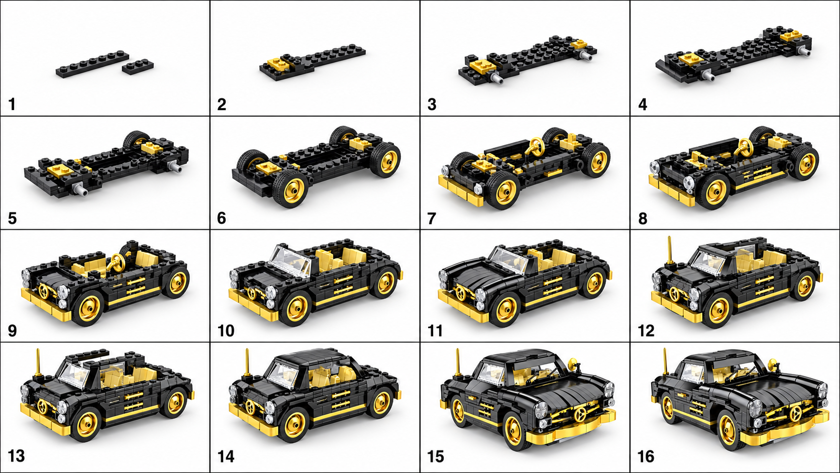
Once you have a model you want to present, a clean photo can become a BrickGPT visual board and short assembly-style clip. This can be useful for a project page or a social post. It does not replace the Studio file, the inventory or the tested instruction PDF.
Inspect the public sample below to understand that distinction. The clip illustrates a model but is not an exported Studio sequence. Compare it with the input photo and decide whether it communicates the features you want to show. Keep links to actual instructions clearly labeled wherever you publish a showcase.
Explore sample outputs
No sign-in required.
Official references and troubleshooting
A photo-only input is the wrong starting point if your goal is a reliable parts list: reconstruct or obtain the actual model first. If the digital model is correct but the test build fails, use the tester’s first point of confusion to decide whether to fix the sequence, the view or the physical connection.
The Studio Help Center is the primary reference for its current interface and Instruction Maker. The LDraw specification documents the file format used by the practice asset. This tutorial is independent of BrickLink and LEGO, and does not claim those organizations reviewed the exercise.